
hotline Service Hotline
0769-22336260
0769-22336260

Dongguan Magnetoelectronics Technology Co. Ltd..
Contact: Miss Zhang
Tel: 0769-22336260
Mailbox: 3468754465@qq.com
Website: www.magpresee.com
Address: Room 102,No.7 Xingye Road,Low Chung,Gaobu Town,Guangdong,Dongguan City,Guangdong province
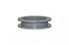
Motor core, English name: Motor core, as the core part of the motor, iron core is the non-professional language of the electrical industry, iron core is also the core. The iron core(magnetic core) plays a pivotal role in the entire motor. It is used to increase the magnetic flux of the inductive coil and has achieved the maximum conversion of electromagnetic power. The motor core is usually a combination of a stator and a rotor. The stator is usually a non-rotating part, and the rotor is usually embedded in the internal position of the stator.
The application range of motor iron core is very wide. Stepping Motors, AC and DC motors, deceleration Motors, external rotor Motors, pole Motors, and synchronous asynchronous motors are all widely used. For the finished motor, Madatiexin plays a key role in the motor accessories. If you want to improve the overall performance of a motor, you need to improve the performance of the motor core. Usually this performance can be solved by improving the material of the core punch, adjusting the magnetic conductivity of the material, and controlling the size of the iron loss.

A good motor core needs to be stamped by a precision metal stamping die, using an automatic riveting process, and then stamped out using a high-precision stamping machine table. The advantage of this is that the plane integrity of its products can be guaranteed to the greatest extent and the product accuracy can be guaranteed to the greatest extent.
The motor core, which is usually of good quality, is used for motor core stamping. High precision hardware continuous stamping die with high speed stamping machine, coupled with excellent professional motor core production personnel, can maximize the production rate of good motor core.

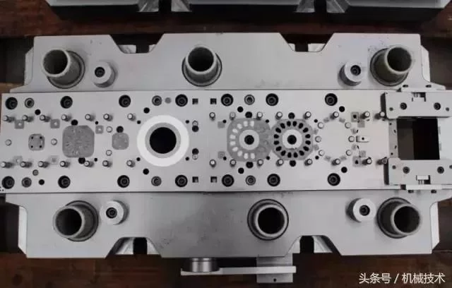
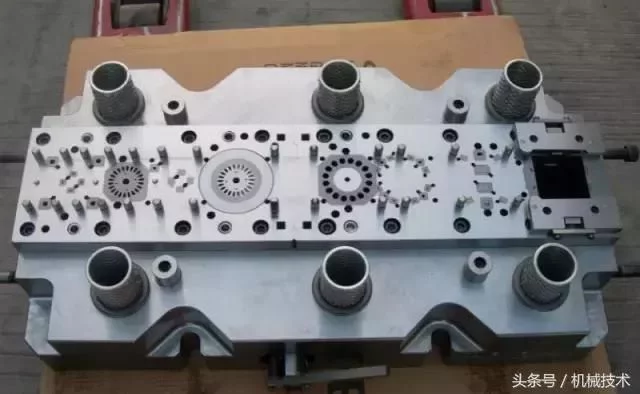
Modern stamping technology is a combination of equipment, molds, materials and processes in a variety of new technology. High speed stamping technology is an advanced forming technology developed in the past 20 years. The modern stamping technology of the rotor core parts of the motor is to use high precision, high efficiency, long life, and multiple work stages of the various processes in a mold to automate the punching on a high-speed punching bed. After the punch process is made of the strip material, After the leveling machine is used for leveling, and then the automatic feed device is used for automatic feed, and then the strip material enters the mold, and the punching, forming, finishing, cutting edge, and iron core automatic stacking can be continuously completed, with twisted and oblique stacking. The punching of the process, bringing back the stacking material, etc.. The finished parts of the iron core are transported from the mold. The entire punching process is automatically completed on a high-speed punching bed(as shown in Figure 1).
With the continuous development of the motor manufacturing process, modern stamping technology has cited the process methods for manufacturing the motor core. Now it is more and more accepted by the manufacturer of the motor, and the processing methods for manufacturing the motor core are also more and more advanced. In foreign countries, generally advanced manufacturers of motors, all use modern stamping technology to punch iron core parts. In China, the processing method of stamping iron core parts with modern stamping technology is being further developed, and this high-tech manufacturing technology is becoming more and more mature. In the motor manufacturing industry, the advantages of this manufacturing motor process have been taken seriously by many manufacturers.. Using modern stamping technology to make iron core parts compared with the original use of ordinary molds and equipment to make iron core parts, it has the characteristics of high automation, high dimensional accuracy, long die service life, etc., and is suitable for large quantities of stamping parts. production. As the multi-position step injection die is a punch of a large number of processing processes on a die, the manufacturing process of the motor is reduced, and the production efficiency of the manufacturing motor is improved.
1, modern high-speed stamping equipment
The precision die of modern high-speed stamping can not be separated from the cooperation of high-speed stamping. At present, the development trend of modern stamping technology at home and abroad is stand-alone automation, mechanization, automatic feeding, automatic unloading, and automatic production. The high-speed stamping technology has been widely developed at home and abroad. The stamping speed of the rotor core of the motor is generally 200-400 times per min, and most of them work within the medium-speed stamping range. The requirements of precision step die for automatic lamination of fixed rotor iron core strip of punch motor for high speed precision stamping press are high precision requirement for the sliding block of punch press at the next dead point because of the influence of the quality problem of forming iron core process automatically in the die. Now precision stamping equipment is developing in the direction of high speed, high precision, and good stability. Especially in recent years, precision high-speed stamping machines have developed rapidly and have played a major role in improving the production efficiency of stamping parts. High speed precision punch is relatively advanced in the design structure, and the manufacturing accuracy is high. It is suitable for high-speed stamping of multi-position hard alloy stage, and can greatly increase the service life of advanced injection die.
The materials pressed by the stage die are in the form of rolls. Therefore, modern stamping equipment has auxiliary devices such as unwinding machines and straightening machines. The automatic feed devices include: roll type, cam, mechanical stepless adjustment type, gear type, and CNC stepless adjustment type. The feed machine and other structural forms, It is used with modern stamping equipment. Due to the high degree of automation and fast speed of modern stamping equipment, in order to fully ensure the safety of the mold during the punching process, modern stamping equipment is equipped with an electrical control system in the event of mistakes, such as the failure of the mold during the punching process. situation, The error signal will be immediately transmitted to the electrical control system, and the electrical control system will send a signal to stop the punch immediately. At present, modern stamping equipment used to punch electric rotor core parts mainly include: Germany: Schulershule, Japan: AIDA high-speed punch, DOBBY high-speed punch, ISIS high-speed punch, United States: MINSTER high-speed punch, Taiwan has: Yu Yu high-speed punch and so on. These precision high-speed punching machines have high feed accuracy, stamping accuracy, stiffness of the machine, and reliable machine safety systems. Their stamping speed is generally in the range of 200 to 600 times per min. It is suitable for making automatic laminate of fixed rotor core of motor and structural parts with twisted oblique and rotary automatic rivet.
2, motor fixed rotor iron core modern punching die technology
2.1 Overview of iron core stage feed mode of motor rotor
In the motor industry, the fixed and rotor iron core is one of the important parts of the electric machine. Its quality directly affects the technical performance of the motor. The traditional method of making iron core is to use common common mold to punch out fixed, rotor punching(pieces), through the fragmentation, and then use rivet riveting, buttoning or argon arc welding to make iron core, for AC motor rotor iron core Still need to be manually twisted out of the groove, Stepping motors require uniform magnetic properties and thickness of the rotor core, and the rotation of the stator core and rotor core is required at a certain angle, such as using traditional methods, the efficiency is low, and the accuracy is difficult to meet the technical requirements. Now, with the rapid development of high-speed stamping technology, high-speed stamping multi-position advance molds have been widely used in the fields of motors and electrical appliances to manufacture automatic folded structural iron cores. Among them, the fixed and rotor core can also have a torsional stack groove, a large angle rotary stack riveting structure between the punching sheets, etc., compared with the ordinary punching die. The multi-position input die has the advantages of high punch precision, high production efficiency, long service life, good accuracy of the size of the forged iron core, easy to achieve automation, and suitable for mass production. It is the direction of precision mold development in the motor industry. The fixed and rotor automatically stacked riveting die has a high manufacturing accuracy, advanced structure, a rotary mechanism with high technical requirements, a counting separation mechanism, and a safety mechanism. Iron core automatic double riveting, rotor twisted oblique double riveting, large angle rotary double riveting punching step is placed on the fixed, rotor stamping material work position. The main parts of the progressive die, convex die, concave die are made of cemented carbide materials, each grinding edge can be washed more than 1.5 million times, the total die life of more than 120 million times.
2. Automatic superposition riveting technology for motor rotor core
The automatic stacking riveting technology on the stage die is to complete the original process of making the iron core(rush out of the piece-piece-riveting) in a mold, that is, to add a new stamping technology on the basis of the stage die. In addition to the requirements for the shape of the punch, such as the shaft hole and the groove hole on the rotor, the stamping positions of the rivet points required for the static and rotor iron core riveting and the counting holes for the separation of the overlapping riveting points have been added. The original loading position of the original setting and rotor is changed to the first loading function, and then each punch piece is then formed into a stacked riveting position during the stacking riveting process and the stacking counting separation process(to ensure the thickness of the core). If the core of a rotor needs to be twisted or slewing riveting, a torsion mechanism or a rotary mechanism shall be attached to the lower die of the rotor or the stator loader. This function is realized by changing or rotating the position of the overlapping riveting point on the punching plate, thus satisfying the technical requirements for automatically completing the stamping riveting and rotary riveting in a mold.

2.2.1 The process of forming an automatic stack of iron cores is to rush out of a geometrically shaped overlapping riveting point on the appropriate part of the fixed and rotor punching piece. The overlapping riveting point is in the form shown in Figure 2. The upper part is a concave hole and the lower part is raised. Then, when the protruding part of the upper punch piece of the same nominal size is embedded into the concave hole of the next punch piece, a "over surplus" naturally forms in the circle where the concave die is tightened in the mold to achieve the purpose of fastening the connection, as shown in Figure 3. In the process of forming the core in the mold, the raised part of the upper riveted point is correctly coincided with the concave hole part of the stack riveting point in the punch position. When the upper piece is affected by the drop mold pressure, The following piece generates two pieces of riveting by the reaction force generated by the friction between its shape and the concave mold wall.
In this way, through the continuous punching of high-speed automatic punch, you can get a neat iron core arranged next to a piece, the burrs are in the same direction and have a certain degree of thickness.
2.2.2 The thickness of the core is controlled by punching through the point of the stack on the last piece at the predetermined number of pieces of the core, so that the core is separated by the predetermined number of pieces, as shown in Figure 4. An automatic stack counting separation device is arranged on the die structure, as shown in Figure 5.
Above the counting module there is a drawing board mechanism. The drawing board is driven by a cylinder. The cylinder action is controlled by the electromagnetic valve. The electromagnetic valve acts according to the instructions issued by the control box. Each stroke signal of the punch is entered into the control box. When it is rushed to the set number of pieces, the control box will send a signal through the solenoid valve and the cylinder to make the drawing plate move, so that the counting convex mode can achieve the purpose of counting separation. That is to say, the purpose of punching holes and not punching holes is achieved at the overlapping riveting point of the punch. The thickness of the stack of the iron core can be set by itself. In addition, the shaft holes of some rotor iron cores are required to be punched into 2 or 3 stage shoulder caisson due to the needs of the supporting structure.
As shown in Figure 6, the same type of iron core with the required shoulder hole process can be used on the stage feed die. The structure of the die is shown in Figure 7.
2.2.3 There are two forms of superstructure of the iron core riveting: the first is a dense superposition type, that is, the superstructure riveting group of iron cores does not need to be pressurized outside the mold, and the superstructure of the iron core riveting can be achieved. The second type is a semi-dense stacking type. There is a gap between the core punching pieces that have been riveted at the time of molding. It also needs to be pressurized again to ensure the binding force.
2.2.4 Establishment and determination of the amount of supercharged riveting: the location of the supercharged riveting point shall be determined according to the geometry of the punch piece, taking into account the electromagnetic properties of the motor and the requirements for its use, It is necessary to consider whether there is interference phenomenon in the position of the convex and concave die panels and the strength problem of the position distance from the edge of the corresponding overlapping pigeonhole. The distribution of the overlapping riveting points on the core should be symmetrical and uniform. The number and size of the overlapping riveting points should be determined according to the required binding force between the core sheets. At the same time, the manufacturing process of the die must be considered. For example, if there is a large angle rotary riveting between the iron core punching pieces, the equal requirements of the overlapping riveting points must also be considered. As shown in Figure 8.2.2.5 The geometry of the core riveting point is:
(a) Cylinearly stacked riveting points, applicable to the superimposed structure of the core;
(b) V-shaped riveting points, which are characterized by the high strength of the connection between the core sheets and are suitable for the dense and semi-dense stacking structures of the core;
(c) L-type overlapping riveting points, which are generally used for torsional and oblique riveting of the rotor core of an AC motor and are suitable for the dense stacking structure of the core;
(d) A trapezoidal stacked riveting point, which is divided into a garden trapezoidal and a long trapezoidal stacked riveting point structure, both of which apply to the dense stacked structure of the core, as shown in Figure 9.2.2.6 Overbalance of the supercharged riveting point: The size of the combined force of the supercharged riveting point is related to the excess of the supercharged riveting point. As shown in Figure 10, the size difference between the outer diameter D and the inner longitude D of the supercharged riveting point convex table(ie, the excess amount), It is determined by the gap between the edge of the extruded riveting point and the concave die. Therefore, selecting the appropriate gap is an important part of ensuring the strength of the core riveting and the ease of overlapping riveting.
2.3 Assembly method of automatic superimposed riveting with fixed rotor core of motor
3.3.1 Direct stacking riveting: When the punch is directly rushed into the blanking die at the rotor or stator blanking step of a one-stage precession die, when the punch sheet is superimposed on the tightening circle under the concave die and the concave die, Each punch piece is fixed together by the overlapping riveting protruding part on each punch piece.
3.3.2 Twisted oblique riveting: Each punch on the core is rotated at a small angle and then riveted. This method of riveting is generally used on the rotor core of the AC motor. The punch process is that after each punch(ie, after the punch is rushed into the drop die), the rotary device consisting of the rotor drop die, the tightening ring, and the rotary sleeve is rotated on the rotor drop step of the step. A small angle, The amount of rotation can be changed and adjusted, that is, after the punch is pushed down, it is riveted to the core, and then the core in the rotary device rotates at a small angle. The core thus produced is riveted and twisted, as shown in Figure 11.There are two kinds of structural forms that drive the rotation device in the mold; The first is the form of rotating structure driven by a stepping motor, as shown in Figure 12.The second is the rotation(ie, the mechanical torsion mechanism) driven by the upper and lower motion of the mold on the mold, as shown in Figure 13.3.3.3 Bring back transposed riveting: Each punch on the core is rotated at a specified angle(usually a large angle) and then superimposed riveting. The rotation angle between punching sheets is generally 45 °, 60 °, 72 °, 90 °, 120 °, 180
This method can compensate the stack accumulation error and improve the magnetic performance of the motor due to the uneven thickness of the stamping material. The punch process is that after each punch(that is, after the punch is rushed into the drop die), on the landing step of the step, by the fall
A specified angle of rotation of a rotary device consisting of a die, a tightening ring, and a rotary sleeve. The specified angle of each rotation must be accurate. That is, after the punch, it is riveted on the core, and then the core in the rotary device rotates at the specified angle. The rotation here is a punching process based on the number of riveting points per punch. There are two kinds of structural forms that drive the rotation device in the mold; The first is the rotation of the crankshaft movement of the high-speed punch bed, which drives the rotary drive device through the universal joint, the connecting flange, and the coupling, and then the rotary drive device drives the rotary device in the mold to rotate. As shown in Figure 14.The second is the rotation driven by the servo motor(need to be equipped with a special appliance controller), as shown in Figure 15. The rotary form on a set of stages can be a single rotary form, a double rotary form, or even a multiple rotary form. The angle of rotation between them can be the same or different.2.3.4 Rotation twist oblique riveting: the rotation of a specified angle between each punch on the core plus a twist angle(usually a large angle + a small angle) is then riveted. This stacking riveting method is used for the core falling. The shape is a round shape. The large rotation is used to compensate for the stack accumulation error caused by the uneven thickness of the punching material. The small twist angle is the rotation required for the performance of the AC motor core. The punching process is the same as the previous punching process. The different forms are large rotation angles and not integers. At present, the common structural form that drives the rotation of the inner rotary device of the mold is driven by a servo motor(it needs to be equipped with a special appliance controller).
3.4 The process of realizing torsional and rotary motion
During the high-speed charging process, when the sliding block of the punch bed is at the next dead point, there is no rotation between the convex and concave modes, so the rotating motion of the torsion mechanism and the rotary mechanism must be a discontinuous motion. And it must be coordinated with the upper and lower movements of the punch slide. The specific requirement for the rotation process is that during each stroke of the punch slide, the sliding block rotates within the crankshaft to a range of 240 ° to 60 °, and the rotating mechanism rotates and is stationary within other angles, as shown in Figure 16. The method of setting the rotation range: if the rotation driven by the rotary drive device is used, the adjustment range is set on the device; If motor driven rotation is used, set on the electrical controller or adjust the contact range through the inductive contactor; If mechanical rotation is used, the scope of the lever rotation is adjusted.3.5 Rotation security institutions
Since the stage die is pressed on a high-speed punching bed, for a rotary die structure with a large angle, if the shape of the fixed and rotor punching pieces is not round, it is a square or shape with a tooth shape, etc.. In order to ensure the correct position of each drop die rotation and ensure the safety of drop die and die parts, a rotary safety mechanism must be set up on the step feed die. Rotation safety institutions are in the form of mechanical safety agencies and electrical safety agencies.
3.6 Structural characteristics of modern punching die of motor rotor core
The main structural characteristics of the motor rotor iron core stage feed die are:
1. The mold adopts a dual guide structure, that is, the upper and lower die seats are guided by four or more large ball guide columns, and each discharging device and the upper and lower mold seats have four small guide columns to guide the mold, ensuring that the mold has a reliable guidance accuracy;
2. From the convenience of manufacturing, testing, maintenance, assembly of technical considerations, the die plate adopts more block structure and combination structure;
3. In addition to the commonly used structures with step input modes such as step guide system, discharge system(composed of the main body of the discharge board and the partial discharge plate), lead material system and safety system(misdelivery detection device), The special structure of the motor core feeding mode: such as the counting separation device(ie, the drawing plate structure device) of the iron core automatic stacking, the structure of the iron core stacking riveting point structure and the structure of the top riveting point of the iron core stacking material, and the pinching of the falling material. Riding structure, torsion or rotary device , safety devices for large rotations, etc.;
4. Due to the common use of cemented carbides in the main parts of the stage die and concave die materials, considering the processing characteristics and the price factors of the material, the convex die adopts a pressure plate type fixed form structure, and the concave die adopts an inlaid type structure form to facilitate assembly and replacement.
3, the present situation and development of the modern stamping technology of motor rotor core
The automatic lamination technology of the motor rotor core was first proposed and developed by the United States and Japan in the 1970s, which made breakthrough progress in the manufacturing technology of the motor core and opened up a new way for high-precision iron core automation production. In the mid-1980s, China began to develop this advanced mold technology, first by digesting and absorbing the practical experience gained from the technology of introducing molds, and then by developing such molds independently. And in the localization aspect has obtained the gratifying achievement, from the original by introducing this kind of mould, to we can develop this kind of high-grade precision mould, has raised the motor industry precision mould technical level. Especially in the past 10 years, with the rapid development of precision mould manufacturing industry in China, modern die punching as a special process equipment is becoming more and more important in modern manufacturing industry. The modern stamping technology of the motor rotor core has also been fully and rapidly developed. At the earliest, only a few state-owned enterprises can design and manufacture such molds. Since then, many companies have been able to design and manufacture such molds, and the development of such precision molds has become increasingly mature. And has begun to export abroad, accelerated the development of China's modern high-speed stamping technology.
At present, the modern die technology of fixed rotor iron core is mainly embodied in the following aspects. Its design and manufacturing level is close to the technical level of similar molds in foreign countries:
1. The overall structure of the motor fixed rotor iron core stage feed die(including dual guide device, unloading device, feed guide device, step distance guide device, limit device, safety inspection device, etc.);
2. Iron core superposition riveting point structure form;
3. Automatic superposition riveting technology, twisted tilt, and rotary technology on stage feed die;
4. The dimension accuracy and core fastness of the core are produced by punching;
5. The manufacturing precision and the setting precision of the main parts on the stage feed die;
6. The degree of selection of standard parts on the mold;
7. Selection of the main parts and materials on the mold;
8. Mold main parts of the processing equipment.
With the continuous development of motor varieties, innovation and renewal of assembly technology, the accuracy requirements for the motor core are getting higher and higher. This puts forward higher technical requirements for the motor core level. Its development trend is:
1. The innovation of die structure should be the main theme of the modern die development of motor rotor core;
2. The overall level of the mould develops toward ultra-high precision and higher technology;
3. Innovation and development of large rotary and twisted oblique riveting technology for motor rotor iron core belt;
4. The development of the rotor core stamping die of the motor is toward the direction of multi-arrangement, no edge, and less edge stamping.
5. With the development of high-speed precision punch technology, the mold should be suitable for higher stamping speed.

Concluding remarks
The use of modern stamping technology to manufacture fixed rotor iron cores for electric motors can greatly improve the level of motor manufacturing technology, especially in automotive Motors, precision stepping Motors, small precision DC motors, and AC Motors. It not only guarantees the high technology performance of these Motors, but also suits the needs of mass production. At present, domestic manufacturers of fixed rotor iron core injection molds are gradually developing, and their design and manufacturing technology are constantly improving, although the level of equipment used to produce such molds is basically the same as in other countries. However, we should see the gap between the design and manufacturing technology of this kind of mold and similar molds abroad. In order to improve the competitiveness of our molds in the international market, we must pay attention to and face this gap.
In addition, we must also see that the modern die for the design and manufacture of the fixed rotor core of the motor must be guaranteed by a number of experienced designers and manufacturers, in addition to modern mould manufacturing equipment, namely precision machining machines. This is the key to manufacturing precision molds. With the internationalization of the manufacturing industry, China's mold industry is rapidly in line with the international standards. It is an inevitable trend for the mold manufacturing industry to improve the specialization of mold products, especially today's rapid development of modern stamping technology. The modern stamping technology of fixed rotor iron core parts will be widely used.


 Taobao Wangwang
