The action of the iron core in the coil-the inductive coil principle with the iron core
Date:2018-03-15
Author:无
Click:
Electromagnetic coil definition
The inductive coil is wound around the insulated tube in a circle by the wire. The wires are insulated from each other, and the insulated tube can be hollow or contain a core or magnetic core, referred to as an inductance. In L, the units are Henry(H), Haohengli(mH), micro Henry(uH), 1H = 10 ^ 3 mH = 10 ^ 6uH.
Filtering, because the switch power supply uses the PWM is a hundred K frequency, and the switch state produces high harmonic interference, high harmonic interference to the power grid and the circuit is contaminated, so it must be filtered out, The high harmonics are filtered out using the open and low frequency partitions of the inductor and the capacitance. Therefore, the inductor must be strung into the switch power supply and the capacitor, inductor equivalent resistor Rl = 2 * PI * f * L, The capacitance equivalent resistance Rc = 1 /(2 * PI * f * C), generally take the inductance 10-50mH(provided that the inductance is not magnetically saturated), the capacitor takes 0.047 uF, 0.1 uF, etc., assuming the inductance takes 10mH, the capacitor takes 0.1 uF, For 1MHz harmonic interference, the inductor Rl = 2 * 3.14 * 1Meg * 10mH = 62.8 Kohm, the capacitor Rc = 1 /(2 * 3.14 * 1Meg * 0.1 uF) = 1.59 Ohm. Obviously, the high-frequency signal will produce a large pressure drop after the inductance, and it will go to the ground through the capacitance bypass, thus filtering out the clutter in both aspects, one from the power circuit and the other from the power grid.
Inductance works using the principle of electromagnetic induction. When an electric current flows through a wire, a certain electromagnetic field is generated around the wire, and the wire itself of this electromagnetic field will sense the wire within this electromagnetic field. The effect on the wire itself that produces the electromagnetic field is called "self-perception"; The effect on other wires in this electromagnetic field is called "mutual perception."
The electrical characteristics of the inductive coil are opposite to those of the capacitor, "high frequency resistance, low frequency access". In other words, high frequency signals encounter great resistance when passing through the inductor coil, which is difficult to pass; The resistance to low-frequency signals passing through it is relatively small, that is, low-frequency signals can pass through it more easily. The inductive coil has almost zero resistance to DC.
Resistance, capacitance, and inductance, they all show a certain degree of resistance to the flow of electrical signals in the circuit. This resistance is called "impedance". The impedance of the inductive coil to the current signal uses the coil's self-perception. The inductive coil is sometimes referred to simply as "inductor" or "coil" and is represented by the letter "L". When winding the inductor coil, the number of coils wound is generally referred to as the "number of turns" of the coil.
The performance index of the inductive coil is mainly the magnitude of the inductance. In addition, the wire winding the inductor coil generally has a certain resistance. Usually this resistance is small and can be ignored. But when the current flowing through some circuits is large, this small resistance of the coil can not be ignored, because a large coil consumes power on this coil, causing the coil to heat up or even burn, so sometimes It is also necessary to consider the power that the coil can withstand
The role of the iron core in the coil
The role of the coil plus iron core is to increase the magnetic field strength. The iron core concentrates the magnetic lines around the coil and circulates from the iron core. Remove the iron core and the magnetic induction between the coils will become smaller. The magnetic circuit, like the circuit, always needs to go where the resistance(resistance) is small. The iron core is much smaller than the magnetic resistance of the air, so the flux travels from the iron core.
The core is magnetized by the magnetic field of the solenoid when the core is inserted inside the solenoid tube. The magnetized core also becomes a magnet, so that the magnetic properties of the solenoid are greatly enhanced because the two magnetic fields are superimposed on each other. In order to make the electromagnet more magnetic, the iron core is usually made into a hoofed shape.
However, it should be noted that the coil on the hoof core is wound opposite, one side clockwise and the other side must be counterclockwise. If the windings are the same, the magnetization of the two rings on the core will cancel each other out, making the core not magnetic. The core of the electromagnet is made of soft iron and can not be made of steel. Otherwise, once the steel is magnetized, it will remain magnetic for a long time and can not be demagnetized. Then the strength of its magnetism can not be controlled by the size of the current and lose the advantages that the electromagnet should have.
Principle of inductive coil with iron core
The inductance is the ratio of the magnetic flux of the wire to the current that produces the alternating flux in and around the wire when the current passes through the wire.
When the DC current is passed through the inductor, only a fixed magnetic line appears around it, and it does not change with time; However, when the current is passed through the loop, the magnetic lines around it will appear to change over time. According to Faraday's law of electromagnetic induction, magnetic bioelectricity, the induced potential is generated at both ends of the changing magnetic wire coil. This induced potential is equivalent to a "new power source." When a closed loop is formed, this induced potential generates an induced current. The law of Lenz knows that the total amount of magnetic lines generated by the induced current is to try to prevent the change of the original magnetic lines. Since the original magnetic line change comes from the change of the external alternating power supply, from the objective effect, the inductor coil has the characteristic of preventing the current change in the AC circuit. The inductive coil has characteristics similar to inertia in mechanics. It is named "self-induction" in electricity, and sparks usually occur at the moment when the switch is opened or the switch is turned on. This is caused by the high induced potential generated by self-inductive phenomena.
In short, when the inductor coil is connected to the AC power supply, the magnetic force line inside the coil will change at all times with the current, causing the coil to continuously generate electromagnetic induction. This electromotive force due to changes in the current of the coil itself is called "self-induced electromotive force."
It can be seen that the inductance is only a parameter related to the number of coils, the size and shape of the coil, and the medium. It is a measure of the inertia of the inductive coil and has nothing to do with the applied current.
Points to Note in the Use of Inductors
1, the use of inductors
Moisture and dryness, ambient temperature, high or low frequency environment, whether the inductor is sensitive or impedance characteristics, etc., should be paid attention.
Frequency characteristics of inductors
At low frequencies, inductors generally exhibit inductive characteristics, which only play the role of energy storage and filter high-frequency characteristics.
However, at high frequencies, its impedance characteristics are obvious. There are energy consumption and fever, and the perceptual effect is reduced. The high-frequency characteristics of different inductors are different.
Inventory of usual electrosensing loops
1, single-layer coil
A single-layer coil is wound around the paper cylinder or gum skeleton in a circle with an insulated wire. Such as transistor radio wave antenna coil.
2, hive coil
If the coil is wound, its plane is not parallel to the rotating surface, but intersects into a certain angle. This coil is called a hive coil. And its rotation one week, the number of times the wire bends back and forth, often referred to as the number of turns. The advantages of Honeycomb winding are small size, small distributed capacitance, and large inductance. The hive coil is made by using a hive winding machine. The more folding points, the smaller the distributed capacitance.
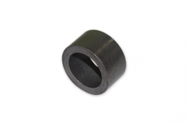
3, ferrite core and iron core coil
The inductance of the coil is related to the presence or absence of a magnetic core. The inclusion of ferrite cores in the empty core coil can increase the inductance and improve the quality factors of the coil.
4, copper core coil
Copper core coils are used in the ultrashort wave range, and the position in the rotating copper core coil is used to change the inductance. This adjustment is more convenient and durable.
5, color code inductor coil
It is a high-frequency inductive coil that is coated with some enamels and then encapsulated with epoxy resin or plastic. Its operating frequency is from 10KHz to 200MHz, and the inductance is generally between 0.1 uH and 3300uH. The color code inductor is an inductor with a fixed inductance, and its inductance marking method is marked with a color ring like a resistor. Its unit is uH.
6, blocking the flow(choke)
The coil that limits the passage of alternating current is called a damper, which is divided into a high-frequency damper and a low-frequency damper.
7, deflection coil
The deflection coil is the load of the TV scanning circuit output stage. The deflection coil requires: high deflection sensitivity, uniform magnetic field, high Q value, small volume, and low price.


 Taobao Wangwang